
Page 174 -
P. 174
164 4 Optical Rotor
with a mixingchamber and an analyzingchamber, a detector of the reaction
products, and outlets for exhaustingsample waste. The analyte specimen and
the reagents will be actuated by pressure force using syringe pumps.
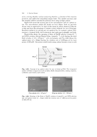
Figure 4.65 shows the mixing part of the microchannel and the optical ro-
tor. The microchannel width and depth are both 50 µm. Such an optically
driven rotor is expected to be used as the mixer in future chemical Labs-on-
a-chip and have the advantage of remote control without the use of bearings.
Reaction results in the mixingpart are analyzed by, for example, optical (fluo-
rescence), thermal [4.24], electrochemical, and mass spectrographic methods.
Figure 4.66a shows the merging of flows of NaOH solution (4 mmol L −1 )
and BTB solution (BromoThymol Blue, 4 mmol L −1 ), both havingthe inlet
3
fluid velocity of 3.3 × 10 µms −1 with surfactants, and Fig. 4.66b shows the
optical mixer (d =20 µm) havingthe rotation rate of 1,000 rpm at the laser
power of 200 mW. The mixer is held stable usingoptical tweezers even in such
Sample
50 mm Waist
Mixer
Reagent
Fig. 4.65. Concept of an optical mixer for use in future µ-TAS. The integrated
system will have components such as inlets, fluidic channels with a mixing chamber,
a detector (not shown)and outlets
(a) (b)
NaOH 1,000 rpm
BTB
3
Flow velocity: 3.3 10 mms -1 Wing top velocity: 1.0 10 mms -1
3
Fig. 4.66. Merging of the flows of NaOH solution (4 mmol/L)and BTB solution
(a),and opticalmixer(d =20 µm)with the rotation rate of 1,000 rpm at the power
of 200 mW (b)