
Page 170 -
P. 170
160 4 Optical Rotor
Unit: mm
54
Z= 0 mm 100 mm s -1
X
5 10
40 Y
23.5
Z
8 mm
X
0
8
20
16 mm
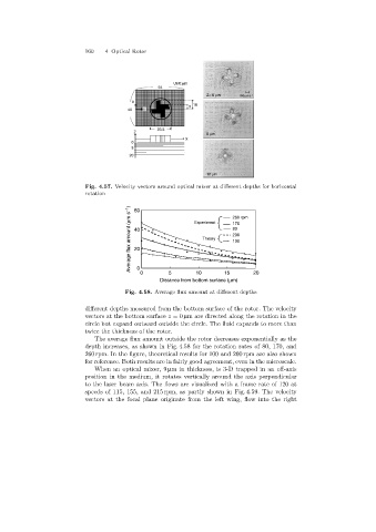
Fig. 4.57. Velocity vectors around optical mixer at different depths for horizontal
rotation 60
Average flux amount (mm s -1 ) 40 Experiment 260 rpm
170
80
200
Theory
100
20
0
5
10
15
0
Distance from bottom surface (mm) 20
Fig. 4.58. Average flux amount at different depths
different depths measured from the bottom surface of the rotor. The velocity
vectors at the bottom surface z =0 µm are directed alongthe rotation in the
circle but expand outward outside the circle. The fluid expands to more than
twice the thickness of the rotor.
The average flux amount outside the rotor decreases exponentially as the
depth increases, as shown in Fig. 4.58 for the rotation rates of 80, 170, and
260 rpm. In the figure, theoretical results for 100 and 200 rpm are also shown
for reference. Both results are in fairly good agreement, even in the microscale.
When an optical mixer, 9 µm in thickness, is 3-D trapped in an off-axis
position in the medium, it rotates vertically around the axis perpendicular
to the laser beam axis. The flows are visualized with a frame rate of 120 at
speeds of 115, 155, and 215 rpm, as partly shown in Fig. 4.59. The velocity
vectors at the focal plane originate from the left wing, flow into the right