
Page 166 -
P. 166
156 4 Optical Rotor
(a) (b) (c)
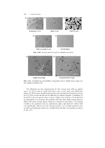
Polystyrene (1 mm) Glass (1 mm) Gold (0.5 mm)
(d) (e)
Aluminum oxide (1 mm) Milk fat colloid
Fig. 4.50. Various particles used to visualize microflow
(a) (b)
rotation
5 mm 5 mm
Single-frame image Composite-frame image
Fig. 4.51. Visualization and pathlines using glass tracers. Single-frame image (a),
and analized pathlines (b)
The followingare the requirements for the tracers used with an optical
rotor. (1) They must be small (less than 1 µm in this case) and sufficiently
dense, (2) The tracers should be prevented from undergoing Brownian motion,
and (3) The tracers should not be affected by optical pressure. Condition (1)
is satisfied with an optical rotor of about 10 µm, and condition (2) is satisfied
by using glycerol to increase the medium viscosity. Since high density glycerol
affects the rotor motion, heavy beads are suitable for the tracer. Concerning
condition (3), particles such as polystyrene, glass, and milk fat colloid were
not significantly affected by the optical pressure, but metallic particles such
as gold and aluminum oxide were expelled from the laser focal point, as shown
in Fig. 4.53.