
Page 163 -
P. 163
4.5 Evaluation 153
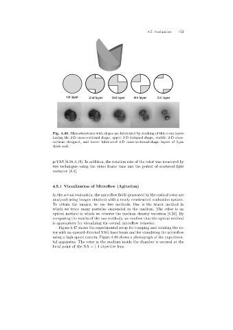
1st layer 2nd layer 3rd layer 4th layer 5th layer
Fig. 4.46. Microstructures with slopes are fabricated by stacking of thin resin layers
having the 2-D cross-sectional shape, upper: 3-D designed shape, middle: 2-D cross-
sections designed, and lower: fabricated 2-D cross-sectional-shape layers of 5 µm
thick each
µ-TAS [4.18,4.19]. In addition, the rotation rate of the rotor was measured by
two techniques usingthe video frame time and the period of scattered light
variation [4.4].
4.5.1 Visualization of Microflow(Agitation)
In the actual evaluation, the microflow fields generated by the optical rotor are
analyzed usingimages obtained with a newly constructed evaluation system.
To obtain the images, we use two methods. One is the tracer method in
which we trace many particles suspended in the medium. The other is an
optical method in which we observe the medium density variation [4.20]. By
comparingthe results of the two methods, we confirm that the optical method
is appropriate for visualizingthe overall microflow behavior.
Figure 4.47 shows the experimental setup for trapping and rotating the ro-
tor with an upward-directed YAG laser beam and for visualizingthe microflow
using a high-speed camera. Figure 4.48 shows a photograph of the experimen-
tal apparatus. The rotor in the medium inside the chamber is secured at the
focal point of the NA = 1.4 objective lens.