
Page 158 -
P. 158
148 4 Optical Rotor
1
0.8
0.6 u =80 mm s -1
u =40 mm s -1
M u =20 mm s -1
0.4 u =10 mm s -1
u =5 mm s -1
Approximated curve
0.2
0
0.0 1.0 2.0 3.0 4.0
D/(Ru)
Fig. 4.39. Similarity of mixing rate M at ω = 0 [4.13] Courtesy of Y. Ogami,
Ritsumeikan Universiry, Japan
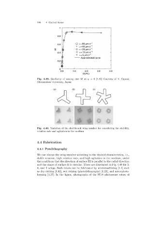
(a) (b) (c)
Fig. 4.40. Variation of the shuttlecock wing number for considering the stability,
rotation rate and agitation in the medium
4.4 Fabrication
4.4.1 Potolithography
We can choose the wingnumber accordingto the desired characteristics, i.e.,
stable rotation, high rotation rate, and high agitation in the medium, under
the conditions that the direction of surface III is parallel to the radial direction
and the shape of surface II is circular. These are illustrated in Fig. 4.40 for 3,
4, and 5 wings. Such rotors can be fabricated by micromachining [1.1] such
as dry etching[1.62], wet etching(photolithography) [1.23], and microphoto-
forming [1.27]. In the figure, photographs of the SU-8 photoresist rotors of