
Page 160 -
P. 160
150 4 Optical Rotor
(a) (b)
Roundness
Swelling
Fig. 4.42. Example of fabricated three-wing rotor shape (a)compared with the
mask shape (b)
400
Three wings
350 Four wings
Rotation rate (rpm) 250 Five wings
300
200
150
100
50
0
2.3 2.8 3.3 3.8 4.3
Exposure time (s)
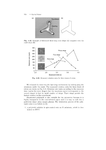
Fig. 4.43. Measured rotation rates for three kinds of rotors
We released the rotor into the laser trap environment by etching away the
aluminum under the resist. The measured rotation rates for three kinds of
rotors are shown in Fig. 4.43. Rotation rate varies according to the exposure
time (varies the rotor shape), but the maximum speed (corresponds to the
correct shape) is fast for small number of wings. Three wings provide the
fastest rotation in this experiment.
Fluorinated polyimide is also suitable for the microrotor because it is
highly transparent in the near-infrared region and it is easy to etch into a
particular shape usingoxygen plasma. The fabrication process of the poly-
imide rotor is as follows [4.16]:
1. a polyimide solution is spin-coated onto an Si substrate, which is then
heated to 370 C
◦