
Page 162 -
P. 162
152 4 Optical Rotor
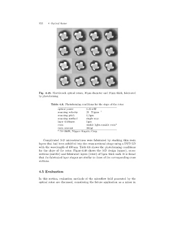
Fig. 4.45. Shuttlecock optical rotors, 30 µmdiameterand 15 µm thick, fabricated
by photoforming
Table 4.6. Photoforming conditions for the slope of the rotor
optical power 0.35 mW
scanning velocity 25−70 µms −1
scanning pitch 0.3 µm
scanning method single scan
layer thickness 5 µm
resin visible light-curable resin a
resin amount 360 µl
a DF-200N, Nippon Kayaku Corp.
Complicated 3-D microstructures were fabricated by stackingthin resin
layers that had been solidified into the cross-sectional shape usinga DVD LD
with the wavelength of 650 nm. Table 4.6 shows the photoforming conditions
for the slope of the rotor. Figure 4.46 shows the 3-D design (upper), cross-
sections (middle) and fabricated layers (lower) of 5 µm thick each. It is found
that the fabricated layer shapes are similar to those of the correspondingcross
sections.
4.5 Evaluation
In this section, evaluation methods of the microflow field generated by the
optical rotor are discussed, consideringthe future application as a mixer in