
Page 161 -
P. 161
4.4 Fabrication 151
2. a Si-based negative resist with high resistance to oxygen reactive ion-beam
etching(O 2 RIE) is spin-coated onto the polyimide layer and exposed to
an electron beam
3. the polyimide layer is etched down to the Si substrate by O 2 RIE
4. after removal of the resist, the microrotor are freed from the substrate by
ultrasonic vibration.
Fluorinated polyimide has a density of 1.49 and a refractive index of 1.53 at
a wavelength of 1.064 µm as listed in Table 3.3.
4.4.2 Microphotoforming
In order to increase the optical torque of the rotor, it is effective to adopt a 3-D
structure with slopes on its upper surface. To fabricate such 3-D microstruc-
tures, photoformingis applied. However, the presently proposed photoforming
apparatus is large and requires a special laser beam (ultra-short-pulsed near-
infrared Ti:sapphire)or special resin (two-photon-absorbed urethane material)
[1.29, 4.17].
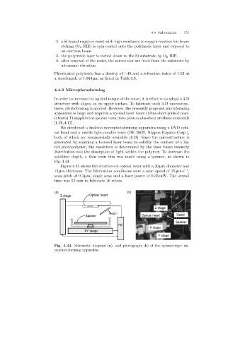
We developed a desktop microphotoformingapparatus usinga DVD opti-
cal head and a visible light-curable resin (DF-200N, Nippon Kayaku Corp.),
both of which are commercially available [4.18]. Since the microstructure is
generated by scanning a focused laser beam to solidify the contour of a liq-
uid photopolymer, the resolution is determined by the laser beam intensity
distribution and the absorption of light within the polymer. To decrease the
solidified depth, a thin resin film was made usinga spinner, as shown in
Fig. 4.44
Figure 4.45 shows the shuttlecock optical rotor with a 30 µm diameter and
15 µm thickness. The fabrication conditions were a scan speed of 25 µms −1 ,
scan pitch of 0.3 µm, single scan and a laser power of 0.35 mW. The overall
time was 12 min to fabricate 16 rotors.
(a) (b)
Z stage Optical head
Z stage
Resin
Spinner Optical head Resin
Spinner
PC
X stage
XY stage
Y stage
Fig. 4.44. Schematic diagram (a), and photograph (b)of the spinner-type mi-
crophotoforming apparatus