
Page 159 -
P. 159
4.4 Fabrication 149
Table 4.5. Fabrication conditions of photolithography
photo resist SU-8-25
spinner condition 1st: 1,000 rpm, 10 s
2nd: 5,000 rpm, 40 s
prebaking a 100 C, 20 min
◦
◦
postbaking a 140 C, 20 min
development 4.1 min
thickness 10 µm
a
Hot plate
(a) (b)
Sacrificed layer (Al) evaporation
Resist (SU-8)
UV light Prebaking
Mask
Rotor shape
Mask Exposure
Adhesion
Resist
Postbaking
Al layer
Residual
Si substrate Development
resist
Stripping
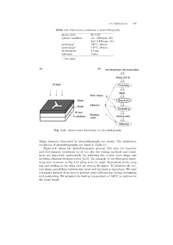
Fig. 4.41. Optical rotor fabrication by photolithography
20 µm diameter fabricated by photolithography are shown. The fabrication
conditions of photolithography are listed in Table 4.5.
Figure 4.41 shows the photolithography process. Not only the exposure
and development conditions [4.14] but also the bakingmethods and condi-
tions are important, particularly for achievingthe correct rotor shape and
avoidingadhesion between rotors [4.15]. An example of the fabricated three-
wingrotor is shown in Fig. 4.42 alongwith the mask. Roundness at the wing
top and swellingat the wingroot are seen in the figure. To fabricate the cor-
rect shape, parallelism between the resist and the mask is important. We used
a hotplate instead of an oven to prevent resist deformation duringprebakeing
and postbaking. We adjusted the baking temperature of 140 C to polymerize
◦
the resist firmly.