
Page 164 -
P. 164
154 4 Optical Rotor
Oblique angle
illumination
Sample
XYZ stage
Objective lens
Observation depth
Lens
High speed
camera
Infrared filter Optical box
YAG laser
Beam expander
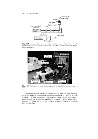
Fig. 4.47. Experimental setup to visualize microflow around mixer. The upward-
directed YAG laser traps the rotor. Generated microflows are visualized with oblique
angle illumination
Oscilloscope
Oblique
illumination
XYZ stage
Ge PD
High-speed Optical fiber
Camera Optical box (YAG laser)
Fig. 4.48. Photograph of experimental apparatus to visualize the microflow around
rotor
To visualize the flow field in the proximity of the rotor, the light scattered
due to the medium density variation upon illumination at a grazing angle is
observed. The oblique illumination increases the image contrast, because only
the scattered light is observed. The sample chamber, in which optical rotors
and milk fat colloid are suspended in water, as shown in Fig. 4.49, is sealed
with a cover glass.