
Page 165 -
P. 165
4.5 Evaluation 155
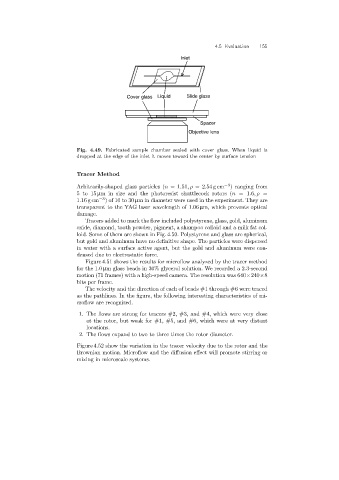
Inlet
Cover glass Liquid Slide glass
Spacer
Objective lens
Fig. 4.49. Fabricated sample chamber sealed with cover glass. When liquid is
dropped at the edge of the inlet it moves toward the center by surface tension
Tracer Method
Arbitrarily-shaped glass particles (n =1.51,ρ =2.54 gcm −3 ) ranging from
5to15 µm in size and the photoresist shuttlecock rotors (n =1.6,ρ =
1.16 gcm −3 )of10to30 µm in diameter were used in the experiment. They are
transparent to the YAG laser wavelength of 1.06 µm, which prevents optical
damage.
Tracers added to mark the flow included polystyrene, glass, gold, aluminum
oxide, diamond, tooth powder, pigment, a shampoo colloid and a milk fat col-
loid. Some of them are shown in Fig. 4.50. Polystyrene and glass are spherical,
but gold and aluminum have no definitive shape. The particles were dispersed
in water with a surface active agent, but the gold and aluminum were con-
densed due to electrostatic force.
Figure 4.51 shows the results for microflow analyzed by the tracer method
for the 1.0 µm glass beads in 30% glycerol solution. We recorded a 2.3-second
motion (71 frames) with a high-speed camera. The resolution was 640×240×8
bits per frame.
The velocity and the direction of each of beads #1 through #6 were traced
as the pathlines. In the figure, the following interesting characteristics of mi-
croflow are recognized.
1. The flows are strongfor tracers #2, #3, and #4, which were very close
at the rotor, but weak for #1, #5, and #6, which were at very distant
locations.
2. The flows expand to two to three times the rotor diameter.
Figure 4.52 show the variation in the tracer velocity due to the rotor and the
Brownian motion. Microflow and the diffusion effect will promote stirringor
mixingin microscale systems.