
Page 157 -
P. 157
4.3 Theoretical Analysis II – Fluid Dynamics 147
1 1
(a) (b)
u = 20 mm s -1
0.8 0.8 u = 40 mm s -1
u = 80 mm s -1
0.6 0.6
M M
0.4 0.4
u =33.33 mm s -1
u =66.66 mm s -1
0.2 u = 100.0 mm s -1 0.2
0 0
0 500 1000 1500 2000 0.0 4.0 8.0
w (rpm) D 10 -11 (m s )
2 -1
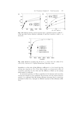
Fig. 4.37. Mixing rateM at various rotation rates ω and fluid velocities u with D =
0(a),and Mat various diffusion coefficients D and fluid velocities u with ω =0
(b)[4.13]
1
0.8
0.6 u = 3.33 mm s -1
M u = 66.66 mm s -1
-1
u = 100.0 mm s
0.4
Additional data
Approximated curve
0.2
0
0.0 100.0 200.0 300.0 400.0 500.0
pRw/(30u)
Fig. 4.38. Similarity of mixing rate M at D = 0, where R is the radius of the
rotor [4.13]. Courtesy of Y. Ogami, Ritsumeikan Universiry, Japan
dependence on the ratio of the diffusion coefficient to u. It is found that the
mixingrate depends on D/u. From these results, an enhancement effect of
convection generated by the rotor and the diffusion of fluids on the mixing
performance is confirmed.
In microscale systems, the flow is considered to be laminar and convective
mixing was considered to be negligible. Nevertheless, from the results obtained
earlier, it is confirmed that the mixingefficiency increases due to convection
generated by the rotor, through the effective increase of the diffusion coeffi-
cient.