Page 155 -
P. 155

4.3 Theoretical Analysis II – Fluid Dynamics  145
                                            5,000
                                                                   CFD
                                            4,000
                                           Rotation rate (rpm)  3,000  P=100 mW
                                                                   Approximation

                                            2,000

                                            1,000

                                               0
                                                2       4       6       8       10
                                                            Height (mm)
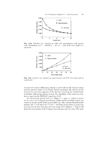
                            Fig. 4.34. Rotation rate obtained by CFD and approximation with parallel
                                                                 ◦
                            beam illumination at P = 100 mW,a =45 , 2r =3 µm with rotor height as a
                            parameter


                                            5,000     CFD
                                           Rotation rate (rpm)   3,000  Approximation
                                            4,000


                                            2,000
                                                                       h=3 mm
                                            1,000
                                                                       P=100 mW
                                               0
                                                0    10    20   30   40   50    60
                                                          Slope angle (deg)
                            Fig. 4.35. Rotation rate obtained by approximation and CDF with slope angle as
                            a parameter


                            second-order central differencingscheme is used both for the viscosity terms
                            and the pressure terms of the Navier–Stokes equation (4.20) and for all the
                            terms of the continuity equation (4.19). For time marching, the implicit back-
                            ward Euler differencingscheme is used. The algorithm of the numerical solu-
                            tion is based on the SIMPLEC algorithm [4.12].
                               The shuttlecock optical rotor (d =20 µm,w =4 µm,t =10 µm) is placed
                            at the center of a Y-shaped microchannel (30 µm width and 20 µm depth) and
                            rotates at speeds of 100–2,000 (typical 500) rpm. The correspondingReynolds
                                            2
                            number (Re = rωd /4π)is10 −2  to 10 −4 . The fluid used is water at room tem-
                            perature and its inlet fluid speed is in the range of 0 to 100 µms −1 . Figure 4.36
                            shows the grid system of the Y-shaped microchannel and the rotor. The mesh
   150   151   152   153   154   155   156   157   158   159   160