
Page 150 -
P. 150
140 4 Optical Rotor
Flux amount horizontal (mm s -1 ) 10 3 2 1 Without slope Flux amount vertical (mm s -1 ) 10 2 1 0 Without slope
(a) 10 4 With slope (b) 10 3 With slope
10
10
10
10
0
10
30
20
10
0
40
30
20
Depth (mm)
Depth (mm)
◦
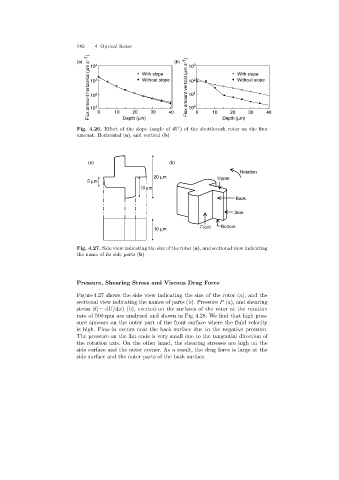
Fig. 4.26. Effect of the slope (angle of 45 )of the shuttlecock rotor on the flux 40
amount. Horizontal (a), and vertical (b)
(a) (b)
Rotation
20 mm Upper
5 mm
10 mm
Back
Side
10 mm Front Bottom
Fig. 4.27. Side view indicating the size of the rotor (a), and sectional view indicating
the name of its side parts (b)
Pressure, Shearing Stress and Viscous Drag Force
Figure 4.27 shows the side view indicating the size of the rotor (a), and the
sectional view indicatingthe names of parts (b). Pressure P (a), and shearing
stress S(= dU/dx) (b), exerted on the surfaces of the rotor at the rotation
rate of 500 rpm are analyzed and shown in Fig. 4.28. We find that high pres-
sure appears on the outer part of the front surface where the fluid velocity
is high. Flow-in occurs near the back surface due to the negative pressure.
The pressure on the flat ends is very small due to the tangential direction of
the rotation axis. On the other hand, the shearingstresses are high on the
side surface and the outer corner. As a result, the dragforce is large at the
side surface and the outer parts of the back surface.