
Page 152 -
P. 152
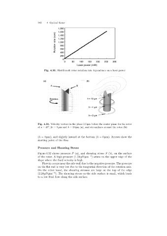
142   4 Optical Rotor
                                           1,800
                                           1,600
                                        Rotation rate (rpm)  1,200
                                           1,400
                                           1,000
                                            800
                                            600
                                            400
                                            200
                                              0
                                               0    50    100   150  200   250   300
                                                        Laser power (mW)
                                 Fig. 4.30. Shuttlecock rotor rotation rate dependence on a laser power


                                (a)                            (b)
                                     A                  B


                                     Rotation                  h = 10 mm

                                                                h = 4 mm


                                                                h = 0 mm


                            Fig. 4.31. Velocity vectors in the plane 0.5 µm before the center plane for the rotor
                            of a =45 , 2r =3 µmand h =10 µm(a), and streamlines around the rotor (b)
                                   ◦

                            (h =4 µm), and slightly inward at the bottom (h =0 µm). Arrows show the
                            startingpoint of the flow.

                            Pressure and Shearing Stress

                            Figure 4.32 shows pressure P (a), and shearingstress S (b), on the surface
                            of the rotor. A high pressure (1.24 pN µm −2 ) arises on the upper edge of the
                            slope where the fluid velocity is high.
                               Flow-in occurs near the side wall due to the negative pressure. The pressure
                            on the flat end is very low due to the tangential direction of the rotation axis.
                            On the other hand, the shearing stresses are large at the top of the edge
                            (2.24 pN µm −2 ). The shearingstress on the side surface is small, which leads
                            to a low fluid flow alongthe side surface.