
Page 156 -
P. 156
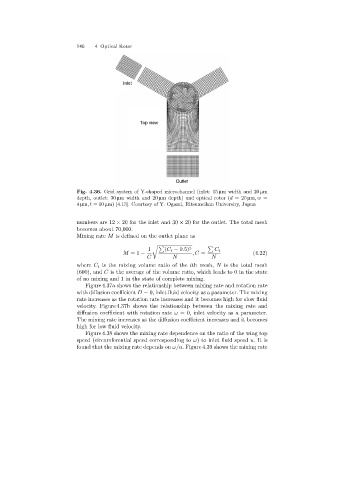
146   4 Optical Rotor


                                            Inlet


                                                  Top view


                                                               Outlet

                            Fig. 4.36. Grid system of Y-shaped microchannel (inlet: 15 µm width and 20 µm
                            depth, outlet: 30 µm width and 20 µm depth)and optical rotor (d =20 µm,w =
                            4 µm,t =10 µm)[4.13]. Courtesy of Y. Ogami, Ritsumeikan Universiry, Japan


                            numbers are 12 × 20 for the inlet and 30 × 20 for the outlet. The total mesh
                            becomes about 70,000.
                            Mixingrate M is defined on the outlet plane as

                                                     1    % (C i − 0.5) 2  %  C i
                                            M =1 −                   ,C =                 (4.22)
                                                     C        N            N
                            where C i is the mixingvolume ratio of the ith mesh, N is the total mesh
                            (600), and C is the average of the volume ratio, which leads to 0 in the state
                            of no mixingand 1 in the state of complete mixing.
                               Figure 4.37a shows the relationship between mixing rate and rotation rate
                            with diffusion coefficient D = 0, inlet fluid velocity as a parameter. The mixing
                            rate increases as the rotation rate increases and it becomes high for slow fluid
                            velocity. Figure 4.37b shows the relationship between the mixing rate and
                            diffusion coefficient with rotation rate ω = 0, inlet velocity as a parameter.
                            The mixingrate increases as the diffusion coefficient increases and it becomes
                            high for low fluid velocity.
                               Figure 4.38 shows the mixingrate dependence on the ratio of the wingtop
                            speed (circumferential speed correspondingto ω) to inlet fluid speed u.Itis
                            found that the mixingrate depends on ω/u. Figure 4.39 shows the mixing rate