
Page 148 -
P. 148
138 4 Optical Rotor
shearingstress S are obtained. On the other hand, in the medium, velocity
U and streamlines are obtained.
Lastly, from the above computational results, the dragforce is calculated
as the sum of the torque components of both the pressure (normal component)
and the shearingstress (tangential component) on all surfaces of the rotor as
2
M drag = (P t + S t )r dr dθ, (4.21)
where P t is the torque component of pressure P, S t is that of the shearing
stress and r is the radius at that point.
4.3.1 Optical Rotor Having a Dissymmetrical Shape on its Side
Velocity Vectors and Streamlines
To evaluate the performance of the optical rotor in water, the streamlines
around the rotor and the viscous dragforce actingon the surface of the rotor
were investigated using a fluid flow solver. The fluid is water (n 1 =1.33)
at 283 K (incompressible viscous flow, density ρ =1.0gcm −3 ,viscosity
2
µ =1.0 mPa s). The correspondingReynolds number (Re = rωd /4π) nearly
equals 10 −4 .
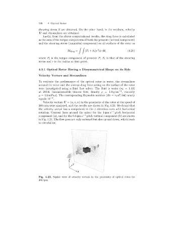
Velocity vectors U =(u, v, w) in the proximity of the rotor at the speed of
200 rpm were analyzed, and the results are shown in Fig. 4.23. We found that
the velocity vector has a component in the z direction even with horizontal
rotation. Contour lines around the mixer for the 1-µms −1 pitch horizontal
component (a), and for the 0.1-µms −1 pitch vertical component (b) are shown
in Fig. 4.24. The flow goes not only outward but also up and down, which leads
to circulation.
Z
Y
X
Fig. 4.23. Squint view of velocity vectors in the proximity of optical rotor for
200 rpm