Page 145 -
P. 145

4.2 Theoretical Analysis I – Optical Torque  135
                                                           Laser


                                                                  Slope
                                                          Rotation


                                                                         III
                                                                        II
                                                      III
                                                                  I
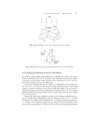
                                     Fig. 4.18. Shuttlecock rotor with slopes on the top surfaces


                                                              Laser
                                                       F
                                                   Normal
                                                   torque
                                                                   III
                                                                   F
                                                       I
                                                                  Reverse
                                                                  torque
                                                             II
                                 Fig. 4.19. Optical torque exerted for the shuttlecock rotor with slopes


                            4.2.3 Enhanced Shuttlecock Rotors with Slopes
                            In order to obtain high torque efficiency, a shuttlecock optical rotor with
                            slopes, as shown in Fig. 4.18, is proposed. The enhanced rotor has the ability
                            to generate optical torque upon parallel beam illumination at not only the
                            side of the wingbut also on the wingslope.
                               In order to simulate the optical torque, we considered a ray incidence on
                            the slope. The ray refracts at the slope, exertingoptical pressure F (generates
                            torque in normal direction), and reflects back side surface III, exerting F
                            (generates torque in the reverse direction) as shown in Fig. 4.19. The optical
                            pressure exerted at bottom surface II and at side surface I are very low owing
                            to low reflectivities.
                               Figure 4.20 shows the simulated results for the enhanced shuttlecock ro-
                            tor for parallel beam illumination with the refractive index of n 2 =1.6. The
                            diameter is d =20 µm, and the thickness is t =10 µm, and the wingwidth is
                            w =3.3 µm. The simulation conditions are listed in Table 4.2 (optical condi-
                            tions are the same as listed in Table 4.1). Fig. 4.20 shows that the total optical
   140   141   142   143   144   145   146   147   148   149   150