Page 140 -
P. 140

130   4 Optical Rotor
                                                              tW(z)


                                                           q        W(z)


                                                                  tW 0
                                                                 W
                                                     z=z f
                                                                   0

                                                               l


                                                             z
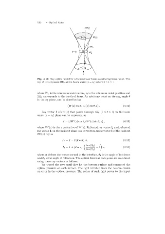
                            Fig. 4.10. Ray optics model for a focused laser beam considering beam waist. The
                            ray of tW(z)passes tW 0 at the beam waist (z = z f )where 0 ≤ t ≤ 1


                            where W 0 is the minimum waist radius, z f is the minimum waist position and
                            2Z 0 corresponds to the depth of focus. An arbitrary point on the ray, angle θ
                            in the xy plane, can be described as

                                                  {W(z)cos θ, W(z)sin θ, z} .             (4.12)

                               Ray vector I of tW(z) that passes through tW 0 (0 ≤ t ≤ 1) on the beam
                            waist (z = z f ) plane can be expressed as


                                              I = {tW (z)cos θ, tW (z)sin θ, z} ,         (4.13)
                            where W (z)isthe z derivative of W(z). Reflected ray vector l r and refracted

                            ray vector l t on the incident plane can be written, usingvector I of the incident
                            tW(z)ray as
                                              I r = I − 2(I • n) n,                       (4.14)

                                                               tan (θ 2 )

                                              I t = I +(I • n)        − 1 n,              (4.15)
                                                               tan (θ 1 )
                            where n defines the vector normal to the interface, θ 1 is the angle of incidence
                            and θ 2 is the angle of refraction. The optical forces at each point are calculated
                            usingthese ray vectors as follows.
                               We traced the rays until they hit the bottom surface and computed the
                            optical pressure on each surface. The light reflected from the bottom causes
                            an error in the optical pressure. The ratios of such light power to the input
   135   136   137   138   139   140   141   142   143   144   145