
Page 135 -
P. 135
4.2 Theoretical Analysis I – Optical Torque 125
y
L
(a) y (b) Objective (r , b)
0
Objective plane x
Element
r R
F
z
0 x z
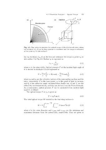
Fig. 4.5. Ray optics to simulate the optical torque of the shuttlecock rotor, where
ray incidence (r L,β)on the lens aperture is considered and the torque is estimated
at the point r R on side surface I
the ray incidence (r L ,β) on the lens and estimated the torque at point r R on
side surface I in Fig. 4.3. Radius r R is expressed as
w
r R = , (4.1)
cos β
where w is the wingwidth. Optical pressure F at the incident light angle of
θ. is derived in Example 3.2 and expressed as
n 1 n 2
F = P (1 + R)cos θ 1 − T cos θ 2 , (4.2)
c n 1
where n 1 and n 2 are the refractive indexes of the surroundingmedium and the
rotor, respectively. P is the laser power, c 0 is the speed of light in vacuum,
and θ 2 is the refractive angle calculated from Snell’s law. R and T are the
reflectivity and transmittivity, and they are derived from the Fresnel formula.
As a consequence, optical pressure F can be calculated if the incident light
angle θ 1 is defined.
The optical torque T at r R is given as
T = r R F sin β. (4.3)
The total optical torque M exerted on the four-wingsurfaces is
−1 2w
β=cos d r L max
2
M =4 F sin αr dr dβ (4.4)
β=0 r L min
where d is the rotor diameter and r L min and r L max are the minimum and
maximum distances from the optical axis, respectively. They are given as