
Page 133 -
P. 133
4.1 Background 123
(a) Ray (b)
Laser
Optical pressure I
II
III
Rotation
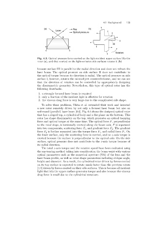
Fig. 4.3. Optical pressure force exerted on the light-incident upper surface lifts the
rotor (a), and that exerted on the light-emission side surfaces rotates it (b)
because surface III is parallel to the radial direction and does not refract the
laser beam. The optical pressure on side surface II does not contribute to
the optical torque because its direction is radial. The optical pressure on side
surface I, however, rotates the microobject counterclockwise, and we can see
that the direction of rotation can be controlled by appropriately designing
the dissymmetric geometry. Nevertheless, this type of optical rotor has the
followingdrawbacks.
1. a strongly focused laser beam is required
2. only a fraction of the incident light is effective for rotation
3. the viscous dragforce is very large due to the complicated side shape.
To solve these problems, Ukita et al. extended their work and invented
a new rotor remotely driven by not only a focused laser beam but also an
unfocused (parallel) laser beam [4.6]. Fig. 4.4 shows the designed optical rotor
that has a sloped top, a cylindrical body and a flat plane on the bottom. This
rotor has shape dissymmetry on the top, which generates an optical trapping
force and optical torque at the same time. The optical force F, perpendicular
to the rotor slope, is torsionally exerted alongthe beam axis. F is separated
into two components, scatteringforce F s , and gradient force F g . The gradient
force F g is further separated into the torque force F t , and radial force F r .On
the lower surface, only the scatteringforce is exerted, and no z-axis torque is
exerted because the surface is perpendicular to the optical axis. On the side
surface, optical pressure does not contribute to the z-axis torque because of
its radial direction.
The total z-axis torque and the rotation speed have been evaluated using
the ray-tracingmethod takinginto consideration the beam waist with various
optical parameters such as the numerical aperture (NA) of the lens and the
laser beam profile, as well as rotor shape parameters includingoblique angle,
height and diameter. As a result, the cylindrical rotor driven by forces exerted
on its top surface is expected to rotate much faster than the previous rotors
[4.3] driven by forces exerted on their side surfaces. This is because all incident
light that hits the upper surface generates torque and also because the viscous
dragforce is small due to the cylindrical structure.