
Page 134 -
P. 134
124 4 Optical Rotor
Laser beam
F
F s
Slope A
F r
F
Side wall t a
Side h
Flat end 2g
F b
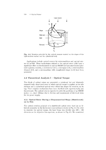
Fig. 4.4. Rotation principle by the optical pressure exerted on the slopes of the
light-incident surface and the cylindrical body
Applications include optical motors for micromachines and optical mix-
ers for µ-TAS. These technologies related to the optical rotor could have a
significant effect on developments in optical MEMS and micromechanical pho-
tonic systems; recently, a micromotor [4.7], a microgear [4.8], a micromachine
element [4.9], and a micromachine with complicated shape [4.10] have been
presented.
4.2 Theoretical Analysis I – Optical Torque
Two kinds of optical rotors are presented: a rotational but not bilaterally
symmetrically structured rotor to which optical torque is applied on its side
surfaces and a cylindrical optical rotor which has slopes for rotation on its
top. Their rotation mechanisms have been clarified both experimentally and
theoretically. The optical rotor is expected to solve the problems of an MEMS
motor, i.e., short lifetime due to friction and requirement of electrical wires
for the power supply.
4.2.1 Optical Rotor Having a Dissymmetrical Shape (Shuttlecock)
on its Side
The optical rotation principle of a shuttlecock optical rotor that has no bi-
lateral symmetry in the horizontal cross-section is shown in Fig. 4.3. In order
to simulate the optical torque, the laser beam was divided into 100 × 100
elements on the objective lens aperture, as shown in Fig. 4.5. We considered