
Page 136 -
P. 136
126 4 Optical Rotor
r L min =0 and r L max = tan{arcsin(NA/n 1 )}, where NA is the numerical
aperture of the objective lens.
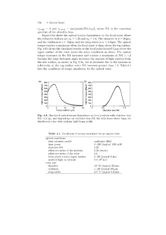
Figure 4.6a shows the optical torque dependence on the focal point where
the refractive indexes are n 1 =1.33 and n 2 =1.6. The diameter is d =20 µm,
and the thickness is t =10 µm, and the wingwidth is w =3.3 µm. The optical
torque reaches a maximum when the focal point is 4 µm above the top surface.
Fig. 4.6b shows the simulated results at the focal point located 5 µmabovethe
upper surface of the rotor under the same conditions as above. The optical
torque increases as the NA increases and reaches a maximum at NA = 1.2
because the large divergent angle increases the amount of light emitted from
the side surface, as shown in Fig. 4.3a, but it decreases due to the increase in
reflectivity at the top surface when NA becomes greater than 1.2. Table 4.1
lists the conditions of torque simulation for the optical rotor.
(a) (b)
800 800
Optical torque (pNmm) 600 Optical torque (pNmm) 600
700
700
500
500
400
400
300
300
200
200
100
0 100 0
0 5 10 15 20 0 0.5 1 1.5
Focus position (mm) Objective lens NA
Fig. 4.6. Simulated optical torque dependence on focal position with objective lens
NA=1.2 (a), and dependence on objective lens NA (b)with focus above 5 µm, for
shuttlecock rotor with uniform light beam profile
Table 4.1. Conditions of torque simulation for an optical rotor
optical conditions
laser intensity profile uniformly filled
laser power 0−200 (typical 100)mW
objective NA 1.25
refractive index of the medium 1.33 (water)
refractive index of the rotor 1.6
focus above a rotor upper surface 0−20 (typical 5) µm
8
speed of light in vacuum 3 × 10 m/s
rotor size
diameter 10−50 (typical 20) µm
thickness 1−20 (typical 10) µm
wing width 2.7−5(typical3.3) µm