
Page 132 -
P. 132
122 4 Optical Rotor
(a) (d)
polystyrene ZnO
(b) (e)
glass Si
(c) (f)
glass GaP
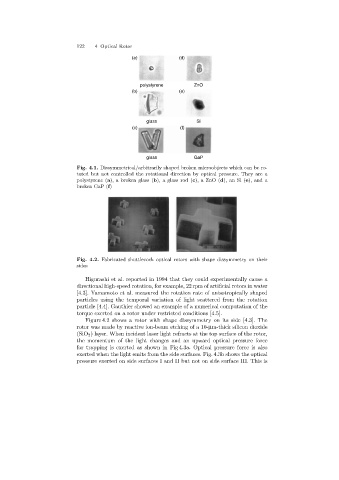
Fig. 4.1. Dissymmetrical/arbitrarily shaped broken microobjects which can be ro-
tated but not controlled the rotational direction by optical pressure. They are a
polystyrene (a), a broken glass (b), a glass rod (c),aZnO(d),anSi(e),anda
broken GaP (f)
Fig. 4.2. Fabricated shuttlecock optical rotors with shape dissymmetry on their
sides
Higurashi et al. reported in 1994 that they could experimentally cause a
directional high-speed rotation, for example, 22 rpm of artificial rotors in water
[4.3]. Yamamoto et al. measured the rotation rate of anisotropically shaped
particles usingthe temporal variation of light scattered from the rotation
particle [4.4]. Gauthier showed an example of a numerical computation of the
torque exerted on a rotor under restricted conditions [4.5].
Figure 4.2 shows a rotor with shape dissymmetry on its side [4.3]. The
rotor was made by reactive ion-beam etchingof a 10-µm-thick silicon dioxide
(SiO 2 ) layer. When incident laser light refracts at the top surface of the rotor,
the momentum of the light changes and an upward optical pressure force
for trappingis exerted as shown in Fig 4.3a. Optical pressure force is also
exerted when the light emits from the side surfaces. Fig. 4.3b shows the optical
pressure exerted on side surfaces I and II but not on side surface III. This is