
Page 142 -
P. 142
132 4 Optical Rotor
1.5
NA = 0.8, z = -1.70 mm
f
= -0.44
NA = 1.0, z f
1
NA = 1.2, z f = -0.09
0.5
Length (mm) -0.5 0
-1
a=20
P=100 mW
-1.5
-1.5 -1 -0.5 0 0.5 1 1.5
Length (mm)
◦
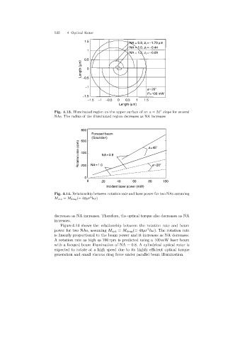
Fig. 4.13. Illuminated region on the upper surface of an a =20 slope for several
NAs. The radius of the illuminated region decreases as NA increases
800
Focused beam
(Gaussian)
600
Rotation rate (rpm) 400 NA =1.0 NA= 0.8 a=45
a=20
200
0
0 20 40 60 80 100
Incident laser power (mW)
Fig. 4.14. Relationship between rotation rate and laser power for two NAs assuming
2
M otp = M drag(= 4πµr hω)
decreases as NA increases. Therefore, the optical torque also decreases as NA
increases.
Figure 4.14 shows the relationship between the rotation rate and beam
2
power for two NAs, assuming M opt = M drag (= 4πµr hω). The rotation rate
is linearly proportional to the beam power and it increases as NA decreases.
A rotation rate as high as 700 rpm is predicted using a 100 mW laser beam
with a focused beam illumination of NA = 0.8. A cylindrical optical rotor is
expected to rotate at a high speed due to its highly efficient optical torque
generation and small viscous drag force under parallel beam illumination.