
Page 201 - A Practical Guide from Design Planning to Manufacturing
P. 201
174 Chapter Six
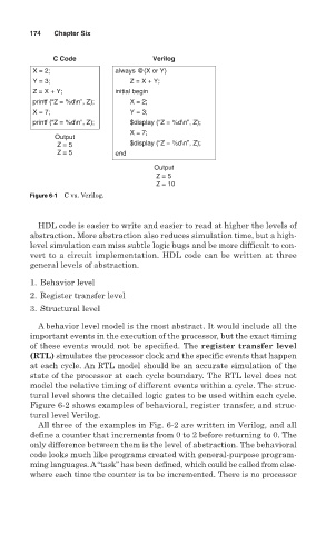
C Code Verilog
X = 2; always @(X or Y)
Y = 3; Z = X + Y;
Z = X + Y; initial begin
printf (“Z = %d\n”, Z); X = 2;
X = 7; Y = 3;
printf (“Z = %d\n”, Z); $display (“Z = %d\n”, Z);
X = 7;
Output
Z = 5 $display (“Z = %d\n”, Z);
Z = 5 end
Output
Z = 5
Z = 10
Figure 6-1 C vs. Verilog.
HDL code is easier to write and easier to read at higher the levels of
abstraction. More abstraction also reduces simulation time, but a high-
level simulation can miss subtle logic bugs and be more difficult to con-
vert to a circuit implementation. HDL code can be written at three
general levels of abstraction.
1. Behavior level
2. Register transfer level
3. Structural level
A behavior level model is the most abstract. It would include all the
important events in the execution of the processor, but the exact timing
of these events would not be specified. The register transfer level
(RTL) simulates the processor clock and the specific events that happen
at each cycle. An RTL model should be an accurate simulation of the
state of the processor at each cycle boundary. The RTL level does not
model the relative timing of different events within a cycle. The struc-
tural level shows the detailed logic gates to be used within each cycle.
Figure 6-2 shows examples of behavioral, register transfer, and struc-
tural level Verilog.
All three of the examples in Fig. 6-2 are written in Verilog, and all
define a counter that increments from 0 to 2 before returning to 0. The
only difference between them is the level of abstraction. The behavioral
code looks much like programs created with general-purpose program-
ming languages. A“task” has been defined, which could be called from else-
where each time the counter is to be incremented. There is no processor