
Page 203 - A Practical Guide from Design Planning to Manufacturing
P. 203
176 Chapter Six
realized in hardware. In the past, this step was always performed by
hand and was one of the most difficult and error-prone steps in chip
design. Today many automated tools exist, which perform these steps
automatically. Some tools allow behavioral models as inputs, but most
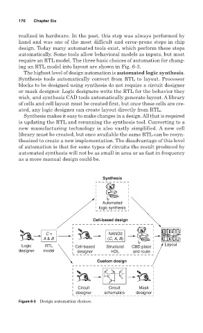
require an RTL model. The three basic choices of automation for chang-
ing an RTL model into layout are shown in Fig. 6-3.
The highest level of design automation is automated logic synthesis.
Synthesis tools automatically convert from RTL to layout. Processor
blocks to be designed using synthesis do not require a circuit designer
or mask designer. Logic designers write the RTL for the behavior they
wish, and synthesis CAD tools automatically generate layout. A library
of cells and cell layout must be created first, but once these cells are cre-
ated, any logic designer can create layout directly from RTL.
Synthesis makes it easy to make changes in a design. All that is required
is updating the RTL and rerunning the synthesis tool. Converting to a
new manufacturing technology is also vastly simplified. A new cell
library must be created, but once available the same RTL can be resyn-
thesized to create a new implementation. The disadvantage of this level
of automation is that for some types of circuits the result produced by
automated synthesis will not be as small in area or as fast in frequency
as a more manual design could be.
Synthesis
Automated
logic synthesis
Cell-based design
C = NAND2
A & B (C, A, B)
Logic RTL Cell-based Structural CBD place Layout
designer model designer HDL and route
Custom design
Circuit Circuit Mask
designer schematics designer
Figure 6-3 Design automation choices.