
Page 220 - A Practical Guide from Design Planning to Manufacturing
P. 220
Logic Design 193
State
01 PS 1
0 1
State State 0 0 0
PS 0
00 10 1 1 d
NS = PS 0
1
Present Next
state state PS 1
0 1
PS 1 PS 0 NS NS 0 0 1 0
1
0 0 0 1 PS 0 1 0 d
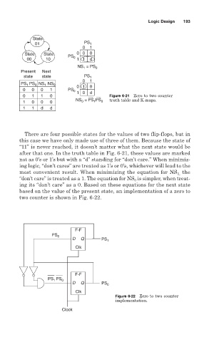
0 1 1 0 Figure 6-21 Zero to two counter
NS = PS PS truth table and K-maps.
1 0 0 0 0 1 0
1 1 d d
There are four possible states for the values of two flip-flops, but in
this case we have only made use of three of them. Because the state of
“11” is never reached, it doesn’t matter what the next state would be
after that one. In the truth table in Fig. 6-21, these values are marked
not as 0’s or 1’s but with a “d” standing for “don’t care.” When minimiz-
ing logic, “don’t cares” are treated as 1’s or 0’s, whichever will lead to the
most convenient result. When minimizing the equation for NS the
1,
“don’t care” is treated as a 1. The equation for NS is simpler, when treat-
0
ing its “don’t care” as a 0. Based on these equations for the next state
based on the value of the present state, an implementation of a zero to
two counter is shown in Fig. 6-22.
F-F
PS 0
D Q PS 1
Clk
F-F
PS PS 0
1
D Q PS 0
Clk
Figure 6-22 Zero to two counter
implementation.
Clock