
Page 236 - A Practical Guide from Design Planning to Manufacturing
P. 236
208 Chapter Seven
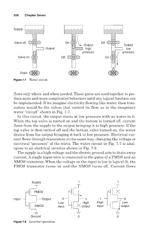
Supply
Valve off On Off
Output Output
Output high low
pressure pressure
Valve on Off On
Drain
Figure 7-7 Water circuit.
flows only where and when needed. These gates are used together to pro-
duce more and more complicated behaviors until any logical function can
be implemented. If we imagine electricity flowing like water, then tran-
sistors would be the valves that control its flow, as in the imaginary
water “circuit” shown in Fig. 7-7.
In this circuit, the output starts at low pressure with no water in it.
When the top valve is turned on and the bottom is turned off, current
flows from the supply to the output bringing it to high pressure. If the
top valve is then turned off and the bottom valve turned on, the water
drains from the output bringing it back to low pressure. Electrical cur-
rent flows through transistors in the same way, changing the voltage or
electrical “pressure” of the wires. The water circuit in Fig. 7-7 is anal-
ogous to an electrical inverter shown in Fig. 7-8.
The supply is a high voltage and the electric ground acts to drain away
current. A single input wire is connected to the gates of a PMOS and an
NMOS transistor. When the voltage on the input is low (a logical 0), the
PMOS transistor turns on and the NMOS turns off. Current flows
Supply 1 1
PMOS
Input Output 0 1 1 0
Low High High Low
NMOS input output input output
Ground 0 0
Figure 7-8 Inverter operation.