
Page 191 - A Practical Guide from Design Planning to Manufacturing
P. 191
164 Chapter Five
front-end pipeline to be decoded and loaded into the trace cache. If there
is a trace cache hit, the trace cache delivers up to 3 uops per cycle. Some
uops read from the trace cache are actually pointers to uop routines
stored in the microcode ROM. In this case, the ROM is read and it
begins feeding uops into the execution pipeline instead. This allows
macroinstructions that must be translated into large numbers of uops
to not take up space in the trace cache.
The uops must then travel across the die to the next step in the exe-
cution pipeline. The Pentium 4 is unusual in that its pipeline allows for
two “drive” cycles where no computation is performed but data is simply
traveling from one part of the die to another. This allows the processor to
achieve very high frequencies while still providing some flexibility in
where the different blocks of the execution pipeline are physically placed
on the die. Designers attempt to create a floorplan where blocks that
communicate often are placed close together, but inevitably every block
cannot be right next to every other block with which it might commu-
nicate. The presence of drive cycles in the pipeline shows how transis-
tor speeds have increased to the point where now simple wire delay is
an important factor in determining a processor’s frequency.
Allocation
The first stop after being fetched from the trace cache is the allocation
step. At this point the uops still reflect the original program order (at
least if branch predictions have been correct). It is important to record
this order before the uops enter the out-of-order portion of the pipeline.
Each uop is allocated an entry in the reorder buffer (ROB). These entries
are allocated in program order and will be retained by each uop until it
is retired or discarded. The Pentium 4 ROB has 126 entries, which
means at one time there are at most 126 uops in the execution pipeline.
If the ROB is full, the allocation step must stall the uops it has and wait
for space to become available before allowing the uops to proceed.
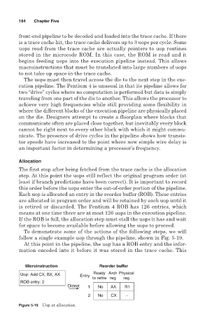
To demonstrate some of the actions of the following steps, we will
follow a single example uop through the pipeline, shown in Fig. 5-19.
At this point in the pipeline, the uop has a ROB entry and the infor-
mation encoded into it before it was stored in the trace cache. This
Microinstruction Reorder buffer
Uop: Add CX, BX, AX Entry Ready Arch Physical
to retire reg reg
ROB entry: 2
Oldest 1 No AX R1
2 No CX –
Figure 5-19 Uop at allocation.