
Page 202 - A Practical Guide from Design Planning to Manufacturing
P. 202
Logic Design 175
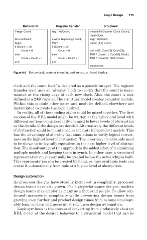
Behavioral Register transfer Structural
integer Count; reg [1:0] Count; module MyCounter (Clock, Count);
input Clock;
task IncCount; always @(posedge Clock) reg [1:0] Count;
begin begin output [1:0] Count;
if (Count == 2) if (Count == 2)
Count = 0; Count = 0; nor (NS0, Count[1], Count[0]);
else else MSFF (Count[1], Count[0], Clock);
Count = Count + 1; Count = Count + 1; MSFF (Count[0], NS0, Clock);
end end
endmodule;
Figure 6-2 Behavioral, register transfer, and structural level Verilog.
clock and the count itself is declared as a generic integer. The register
transfer level uses an “always” block to specify that the count is incre-
mented at the rising edge of each new clock. Also, the count is now
defined as a 2-bit register. The structural model creates a counter module.
Within this module other gates and modules defined elsewhere are
instantiated to create the logic desired.
In reality, all of these coding styles could be mixed together. The first
version of the HDL model might be written at the behavioral level with
different sections being gradually changed to lower levels of abstraction
as the details of the design are decided. Alternatively the different levels
of abstraction could be maintained as separate independent models. This
has the advantage of allowing fast simulations to verify logical correct-
ness on the highest level of abstraction. The lower-level models only need
to be shown to be logically equivalent to the next higher level of abstrac-
tion. The disadvantage of this approach is the added effort of maintaining
multiple models and keeping them in synch. In either case, a structural
representation must eventually be created before the actual chip is built.
This representation can be created by hand, or logic synthesis tools can
create it automatically from code at a higher level of abstraction.
Design automation
As processor designs have steadily increased in complexity, processor
design teams have also grown. For high-performance designs, modern
design teams may employ as many as a thousand people. To allow con-
tinued increases in complexity while preventing design teams from
growing even further and product design times from become unaccept-
ably long, modern engineers must rely upon design automation.
Logic synthesis is the process of converting from a relatively abstract
HDL model of the desired behavior to a structural model that can be