
Page 23 - Microtectonics
P. 23
10 2 · Flow and Deformation
2.1 2.1
Introduction
A hunter who investigates tracks in muddy ground near
a waterhole may be able to reconstruct which animals
arrived last, but older tracks will be partly erased or
modified. A geologist faces similar problems to recon-
struct the changes in shape that a volume of rock under-
went in the course of geological time, since the end prod-
ucts, the rocks that are visible in outcrop, are the only
direct data source. In many cases it is nevertheless pos-
sible to reconstruct at least part of the tectonic history
of a rock from this final fabric. This chapter treats the
change in shape of rocks and the methods that can be
used to investigate and describe this change in shape.
This is the field of kinematics, the study of the motion of
particles in a material without regard to forces causing
the motion. This approach is useful in geology, where
usually very little information can be obtained concern-
ing forces responsible for deformation. In order to keep
the discussion simple, the treatment is centred on flow
and deformation in two dimensions.
2.2 2.2
Terminology
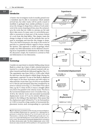
Consider an experiment to simulate folding using viscous
fluids in a shear rig. A layer of dark-coloured material is
inserted in a matrix of light-coloured material with an-
other viscosity and both are deformed together (Fig. 2.1).
The experiment runs from 10.00 to 11.00 h, after which
the dark layer has developed a folded shape. During the
experiment, a particle P in one of the fluids is displaced
with respect to the shear rig bottom and with respect to
other particles. At any time, e.g. at 10.10 h, we can attribute
to P a velocity and movement direction, visualised by an
arrow or velocity vector (Fig. 2.1). If we follow P for a short
time, e.g. for 5 s from 10.10 h, it traces a straight (albeit
very short) line parallel to the velocity vector. This line is
the incremental displacement vector. At another time, e.g.
10.40 h, the velocity vector and associated incremental
displacement vector of P can be entirely different (e.g.
related to the folding of the dark layer). This means that
the displacement path followed by P to its final position
at 11.00 h is traced by a large number of incremental dis-
placement vectors, each corresponding to a particular
Fig. 2.1. Schematic presentation of the velocity, incremental displace-
ment and finite displacement of a particle P in a deformation ex-
periment in a shear box. Velocity of P at 10.10 h and 10.40 h can be
illustrated as a velocity vector. If deformation proceeds over 5 sec-
onds, the incremental displacement vector will be parallel to the ve-
locity vector. The sequence of incremental displacement vectors gives
the finite displacement path. The finite displacement vector is dif-
ferent and connects initial (10.00 h) and final (11.00 h) positions of P