
Page 26 - Microtectonics
P. 26
2.4 · Reference Frames 13
2.3 2.3
Description and Reconstruction of Deformation
It is interesting to consider how we could accurately de-
scribe velocities and displacement of particles in the ex-
periment of Fig. 2.1 using a film (Fig. 2.2). Intuitively, one
would assume that the film gives a complete and accu-
rate picture of the experiment, and that no further prob-
lems occur in reconstruction of flow and deformation.
However, such a reconstruction is more difficult than it
would seem. If we compare stages of the experiment that
are far apart in time, e.g. at 10.00, 10.30 and 11.00 h, we
can connect positions of particles by vectors which de-
fine the finite deformation pattern (Fig. 2.2 bottom).
However, these finite deformation patterns carry no in-
formation on the history of the deformation, i.e. on the
displacement paths of individual particles. Finite displace-
ment paths have to be reconstructed from incremental
deformation patterns; if we take two stages of the ex-
periment that are close together in time, e.g. two subse-
quent images of the film (Fig. 2.2 top), these can be used
to find the incremental deformation pattern. Finite dis-
placement paths can be accurately reconstructed by add-
ing all incremental deformation patterns. This is obvi-
ously impossible in practice. An approximation can be
obtained by adding a selection of incremental deforma-
tion patterns, or a number of finite deformation patterns
which represent short time periods. The flow pattern at
particular stages of the deformation can be reconstructed
from the incremental deformation patterns since these
have the same shape.
2.4 2.4
Reference Frames
The flow, incremental and finite deformation patterns in
Fig. 2.2 were produced with a camera fixed to an immo-
bile part of the shear rig. The shear rig acts as a refer-
ence frame. However, the patterns would have a different
shape if another reference frame were chosen. Figure 2.3
shows three possible arrangements for reconstruction of
finite deformation patterns from two photographs taken
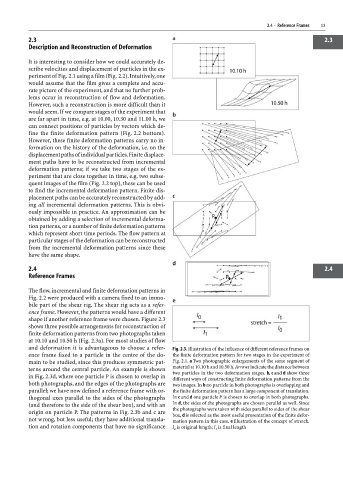
at 10.10 and 10.50 h (Fig. 2.3a). For most studies of flow
and deformation it is advantageous to choose a refer- Fig. 2.3. Illustration of the influence of different reference frames on
ence frame fixed to a particle in the centre of the do- the finite deformation pattern for two stages in the experiment of
main to be studied, since this produces symmetric pat- Fig. 2.1. a Two photographic enlargements of the same segment of
material at 10.10 h and 10.50 h. Arrows indicate the distance between
terns around the central particle. An example is shown
two particles in the two deformation stages. b, c and d show three
in Fig. 2.3d, where one particle P is chosen to overlap in
different ways of constructing finite deformation patterns from the
both photographs, and the edges of the photographs are two images. In b no particle in both photographs is overlapping and
parallel; we have now defined a reference frame with or- the finite deformation pattern has a large component of translation.
thogonal axes parallel to the sides of the photographs In c and d one particle P is chosen to overlap in both photographs.
(and therefore to the side of the shear box), and with an In d, the sides of the photographs are chosen parallel as well. Since
the photographs were taken with sides parallel to sides of the shear
origin on particle P. The patterns in Fig. 2.3b and c are box, d is selected as the most useful presentation of the finite defor-
not wrong, but less useful; they have additional transla- mation pattern in this case. e Illustration of the concept of stretch.
tion and rotation components that have no significance l is original length; l is final length
1
o