
Page 27 - Microtectonics
P. 27
14 2 · Flow and Deformation
Box 2.2 How to use reference frames
The world in which we live can only be geometrically described if
we use reference frames. A reference frame has an origin and a
particular choice of reference axes. If a choice of reference frame X
is made, measurements are possible if we define a coordinate sys-
tem within that reference frame such as scales on the axes and/or
angles between lines and reference frame axes. Usually, we use a
Cartesian coordinate system (named after René Descartes) with Y
three orthogonal, straight axes and a metric scale.
In daily life we intuitively work with a reference frame fixed to
the Earth’s surface and only rarely become confused, such as when
we are in a train on a railway station next to another train; it can
then be difficult to decide whether our train, the other train, or both
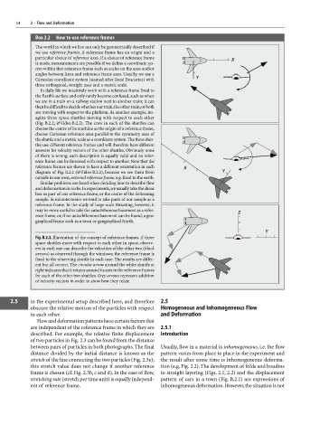
are moving with respect to the platform. As another example, im-
agine three space shuttles moving with respect to each other
(Fig. B.2.2, ×Video B.2.2). The crew in each of the shuttles can
choose the centre of its machine as the origin of a reference frame,
choose Cartesian reference axes parallel to the symmetry axes of
the shuttle and a metric scale as a coordinate system. The three shut-
tles use different reference frames and will therefore have different
answers for velocity vectors of the other shuttles. Obviously none
of them is wrong; each description is equally valid and no refer-
ence frame can be favoured with respect to another. Note that the
reference frames are shown to have a different orientation in each X
diagram of Fig. B.2.2 (×Video B.2.2), because we see them from Y
outside in our own, external reference frame, e.g. fixed to the earth.
Similar problems are faced when deciding how to describe flow
and deformation in rocks. In experiments, we usually take the shear
box as part of our reference frame, or the centre of the deforming
sample. In microtectonics we tend to take parts of our sample as a
reference frame. In the study of large-scale thrusting, however, it
may be more useful to take the autochthonous basement as a refer- Z
ence frame, or, if no autochthonous basement can be found, a geo-
graphical frame such as a town or geographical North.
Y
Fig. B.2.2. Illustration of the concept of reference frames. If three
space shuttles move with respect to each other in space, observ-
ers in each one can describe the velocities of the other two (black
arrows) as observed through the windows; the reference frame is
fixed to the observing shuttle in each case. The results are differ-
ent but all correct. The circular arrow around the white shuttle at
right indicates that it rotates around its axis in the reference frames
for each of the other two shuttles. Grey arrows represent addition
of velocity vectors in order to show how they relate
2.5 in the experimental setup described here, and therefore 2.5
obscure the relative motion of the particles with respect Homogeneous and Inhomogeneous Flow
to each other. and Deformation
Flow and deformation patterns have certain factors that
are independent of the reference frame in which they are 2.5.1
described. For example, the relative finite displacement Introduction
of two particles in Fig. 2.3 can be found from the distance
between pairs of particles in both photographs. The final Usually, flow in a material is inhomogeneous, i.e. the flow
distance divided by the initial distance is known as the pattern varies from place to place in the experiment and
stretch of the line connecting the two particles (Fig. 2.3e); the result after some time is inhomogeneous deforma-
this stretch value does not change if another reference tion (e.g. Fig. 2.2). The development of folds and boudins
frame is chosen (cf. Fig. 2.3b, c and d). In the case of flow, in straight layering (Figs. 2.1, 2.2) and the displacement
stretching rate (stretch per time unit) is equally independ- pattern of cars in a town (Fig. B.2.1) are expressions of
ent of reference frame. inhomogeneous deformation. However, the situation is not