
Page 34 - Microtectonics
P. 34
2.11 · Stress and Deformation 21
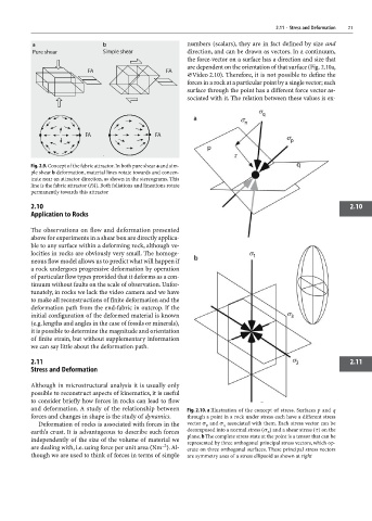
numbers (scalars), they are in fact defined by size and
direction, and can be drawn as vectors. In a continuum,
the force-vector on a surface has a direction and size that
are dependent on the orientation of that surface (Fig. 2.10a,
×Video 2.10). Therefore, it is not possible to define the
forces in a rock at a particular point by a single vector; each
surface through the point has a different force vector as-
sociated with it. The relation between these values is ex-
Fig. 2.9. Concept of the fabric attractor. In both pure shear a and sim-
ple shear b deformation, material lines rotate towards and concen-
trate near an attractor direction, as shown in the stereograms. This
line is the fabric attractor (FA). Both foliations and lineations rotate
permanently towards this attractor
2.10 2.10
Application to Rocks
The observations on flow and deformation presented
above for experiments in a shear box are directly applica-
ble to any surface within a deforming rock, although ve-
locities in rocks are obviously very small. The homoge-
neous flow model allows us to predict what will happen if
a rock undergoes progressive deformation by operation
of particular flow types provided that it deforms as a con-
tinuum without faults on the scale of observation. Unfor-
tunately, in rocks we lack the video camera and we have
to make all reconstructions of finite deformation and the
deformation path from the end-fabric in outcrop. If the
initial configuration of the deformed material is known
(e.g. lengths and angles in the case of fossils or minerals),
it is possible to determine the magnitude and orientation
of finite strain, but without supplementary information
we can say little about the deformation path.
2.11 2.11
Stress and Deformation
Although in microstructural analysis it is usually only
possible to reconstruct aspects of kinematics, it is useful
to consider briefly how forces in rocks can lead to flow
and deformation. A study of the relationship between Fig. 2.10. a Illustration of the concept of stress. Surfaces p and q
forces and changes in shape is the study of dynamics. through a point in a rock under stress each have a different stress
Deformation of rocks is associated with forces in the vector σ p and σ q associated with them. Each stress vector can be
earth’s crust. It is advantageous to describe such forces decomposed into a normal stress (σ ) and a shear stress (τ) on the
n
plane. b The complete stress state at the point is a tensor that can be
independently of the size of the volume of material we represented by three orthogonal principal stress vectors, which op-
–2
are dealing with, i.e. using force per unit area (Nm ). Al- erate on three orthogonal surfaces. These principal stress vectors
though we are used to think of forces in terms of simple are symmetry axes of a stress ellipsoid as shown at right