
Page 271 - Modelling in Transport Phenomena A Conceptual Approach
P. 271
8.2. ENERGY TRANSPORT WITHOUT CONVECTION 251
Note that Eq. (D) in Table 8.1 is expressed as
(8.2-11)
-
kA
Comparison of Eq. (8.2-11) with Eq. (8.2-10) indicates that
Driving force = To - TL (8.2- 12)
L Thickness
Resistance = - = (8.2-13)
kA (Transport property)(Area)
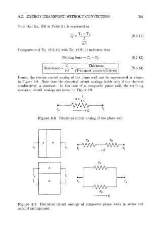
Hence, the electric circuit analog of the plane wall can be represented as shown
in Figure 8.8. Note that the electrical circuit analogy holds only if the thermal
conductivity is constant. In the case of a composite plane wall, the resulting
electrical circuit analogs are shown in Figure 8.9.
Figure 8.8 Electrical circuit analog of the plane wall.
Figure 8.9 Electrical circuit analogs of composite plane walls in series and
parallel arrangement.