
Page 272 - Modelling in Transport Phenomena A Conceptual Approach
P. 272
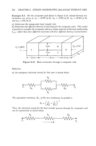
252   CHAPTER 8.  STEADY MICROSCOPIC BALANCES WITHOUT GEN.

            Example 8.4  For the composite wall shown in Figure 8.10, related thermal wn-
            ductivities  are given  as kA = 35W/ m. K,  kg = 12 W/ m. K,  kc = 23 W/ m. K,
            and  ko = 5 W/ m. K.
            a) Determine the steady-state  heat transfer rate.
            b) Determine the effective thermal conductivity for the composite walls.  This makes
            it possible to consider the composite wall as a single material of thermal conductivity
            k,-f, rather than four different materials with four different thermal conductivities.


                       Figure  8.10  Heat conduction through a composite wall.


            Solution
            a) An analogous electrical circuit for this cwe is shown below:


             The equivalent  resistance, R,,  of  the two resistances in parallel is

                                                       -1
                                      Ro=($+&)

             Thus, the electrical analog for the heat transfer process through the composite wall
             can be  represented  as shown below: