
Page 288 - Modelling in Transport Phenomena A Conceptual Approach
P. 288
268 CHAPTER 8. STEADY MICROSCOPIC BALANCES WITHOUT GEN.
around 3 W/ m2. K. Therefore, the maximum value of the critical radius is approx-
imately 3.3cm, and in most practical applications, this will not pose a problem.
Therefore, critical radius of insulation is of importance only for small diameter
wires or tubes.
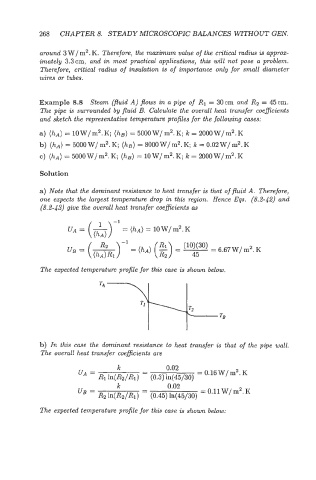
Example 8.8 Steam (fluid A) flows in a pipe of R1 = 30cm and R2 = 45cm.
The pipe is surrounded by fluid B. Calculate the overall heat transfer coefficients
and sketch the representative temperature profiles for the following cases:
a) (hA) =10W/m2.K; (hB)=5000W/m2.K k=2000W/m2.K
b) (hA) = 5000 W/ m2. K; (hB) = 8000 W/m2. K; k = 0.02 W/ m2. K
c) (hA) = 5000W/m2.K; (hB) = 10W/m2.K; k = 2000W/m2.K
Solution
a) Note that the dominant resistance to heat transfer .is that of fluid A. Therefore,
one expects the largest temperature drop in this region. Hence Eqs. (8.2-42) and
(8.2-43) give the overall heat transfer coeficients (1s
uA = (h) =
-1
= (h~) 10W/m2.K
-1
UB = (-) R2 = (hA) (2) o(3o) =6.67W/m2.K
=
(hA )R1 45
The expected temperature profile for this me is shown below.
b) In this case the dominant resistance to heat transfer is that of the pipe wall.
The overall heat transfer coeficients are
k - 0.02
VA = = 0.16 W/ m2. K
R1 ln(R2IR1) - (0.3) 1n(45/30)
k 0.02
UB = - = 0.11 W/ m2. K
R2 ln(RzlR1) - (0.45) ln(45/30)
The expected temperature profile for this case is shown below: