
Page 61 - Modelling in Transport Phenomena A Conceptual Approach
P. 61
42 CHAPTER 3. INTERPHASE TRANSPORT
- L ,
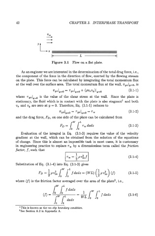
Figure 3.1 Flow on a flat plate.
As an engineer we are interested in the determination of the total drag force, i.e.,
the component of the force in the direction of flow, exerted by the flowing stream
on the plate. This force can be calculated by integrating the total momentum flux
at the wall over the surface area. The total momentum flux at the wall, 7ryZly=o, is
(3.1-1)
where 7yzly,o is the value of the shear stress at the wall. Since the plate is
stationary, the fluid which is in contact with the plate is also stagnant' and both
v, and vy are zero at y = 0. Therefore, Eq. (3.1-1) reduces to
(3.1-2)
and the drag force, FD, on one side of the plate can be calculated from
FD = Jd" Jd" Tw dxdz (3.1-3)
Evaluation of the integral in Eq. (3.1-3) requires the value of the velocity
gradient at the wall, which can be obtained from the solution of the equations
of change. Since this is almost an impossible task in most cases, it is customary
in engineering practice to replace rw by a dimensionless term called the fnction
factor, f, such that
I 1 I
(3.1-4)
Substitution of Eq. (3.1-4) into Eq. (3.1-3) gives
L
FD = 1 pv& Jd" Jd f dxdz = (WL) (3.1-5)
2
where (f) is the friction factor averaged over the area of the plate2, i.e.,
rW rL
f dxdz
& Jd" 1" f dxdz (3.1-6)
'This is known as the no-slip boundary condition.
2See Section A.2 in Appendix A.