
Page 217 - Modern Control Systems
P. 217
Section 3.7 The Time Response and the State Transition Matrix 191
•V|<(» Initial *»((>)
U(s) O O VJs)
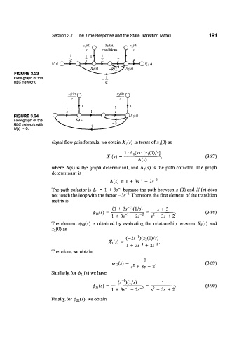
FIGURE 3.23
Flow graph of the
RLC network.
Al(0) A ,(0)
FIGURE 3.24 X,ls)
Flow graph of the
RLC network with
U(s) = 0.
signal-flow gain formula, we obtain X\(s) in terms of x^O) as
1-^(5)-[^(0)/5]
X^s) = (3.87)
A(5)
where A(5) is the graph determinant, and A T(5) is the path cofactor. The graph
determinant is
2
A (5) = 1 + 3s" 1 + 2s" .
_1
The path cofactor is A 2 = 1 + 35 because the path between *i(0) and Xi(s) does
- 1
-
not touch the loop with the factor 35 . Therefore, the first element of the transition
matrix is
l
(1 + 3s' )(l/s) 5 + 3
<f>u(s) 1 -2 2 (3.88)
1 + 35" + 25 " 5 + 3s + 2
The element 4>n(s) is obtained by evaluating the relationship between X](s) and
x 2(0) as
1
(-25' )(x 2 (0)/5)
X l(s) = _1 2
1 + 35 + 25" '
Therefore, we obtain
- 2
(3.89)
s* + 3s + 2
Similarly, for <f>2i(s) we have
(5^)(1/5) 1
02i (s) = 1 2 2 (3.90)
1 + 35" + 25" 5 + 35 + 2
Finally, for cf> 22(s), we obtain