Page 122 - Modern Control of DC-Based Power Systems
P. 122

86                                  Modern Control of DC-Based Power Systems
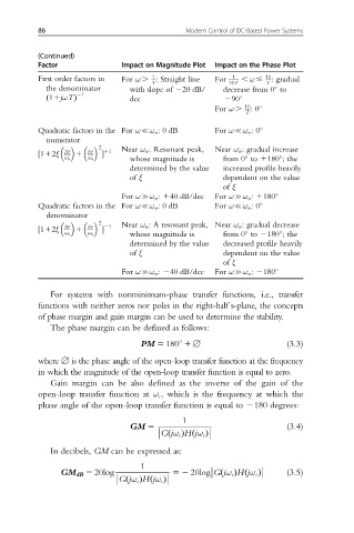

          (Continued)
          Factor               Impact on Magnitude Plot  Impact on the Phase Plot
                                      1
          First order factors in  For ω . : Straight line  For  1  , ω #  10 : gradual
                                      T                  10T      T
            the denominator      with slope of 220 dB/  decrease from 0 to

                    21
                                 dec                    290
            ð 11jωTÞ
                                                     For ω .  10 :0
                                                             T
          Quadratic factors in the For ω{ω n : 0 dB  For ω{ω n :0
            numerator
                         2     Near ω n : Resonant peak,  Near ω n : gradual increase
          ½112ξ  jω  1  jω  11
                 ω n  ω n  Š     whose magnitude is    from 0 to 1180 ;the


                                 determined by the value  increased profile heavily
                                 of ξ                  dependent on the value
                                                       of ξ
                               For ωcω n : 140 dB/dec  For ωcω n : 1180
          Quadratic factors in the For ω{ω n : 0 dB  For ω{ω n :0
            denominator
                         2     Near ω n : A resonant peak, Near ω n : gradual decrease
          ½112ξ  jω  1  jω  21
                 ω n  ω n  Š     whose magnitude is    from 0 to 2180 ;the


                                 determined by the value  decreased profile heavily
                                 of ξ                  dependent on the value
                                                       of ξ
                               For ωcω n : 240 dB/dec  For ωcω n : 2180
             For systems with nonminimum-phase transfer functions, i.e., transfer
          functions with neither zeros nor poles in the right-half s-plane, the concepts
          of phase margin and gain margin can be used to determine the stability.
             The phase margin can be defined as follows:

                                   PM 5 180 1[                         (3.3)

          where [ is the phase angle of the open-loop transfer function at the frequency
          in which the magnitude of the open-loop transfer function is equal to zero.
             Gain margin can be also defined as the inverse of the gain of the
          open-loop transfer function at ω c , which is the frequency at which the
          phase angle of the open-loop transfer function is equal to 2180 degrees:
                                             1
                                                                       (3.4)
                                 GM 5

                                          ð
                                        Gjω c ÞHjω c Þ
                                                ð
             In decibels, GM can be expressed as:
                                   1
                                                                       (3.5)

                GM dB 5 20log               52 20log Gjω c ÞHjω c Þ
                                                       ð
                                                             ð

                                ð
                                      ð
                              Gjω c ÞHjω c Þ
   117   118   119   120   121   122   123   124   125   126   127