
Page 134 - Modern Control of DC-Based Power Systems
P. 134
98 Modern Control of DC-Based Power Systems
V 0
I
Conv 1 1
I 0
Load
I
Conv 2 2
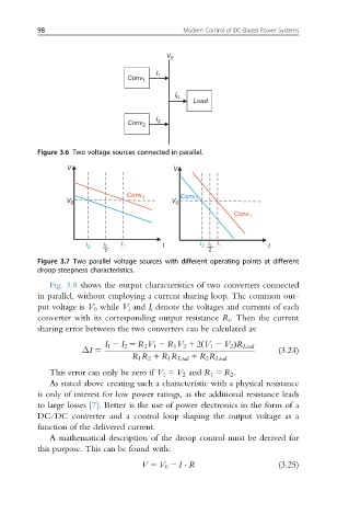
Figure 3.6 Two voltage sources connected in parallel.
V V
Conv 1
V 0 V 0 Conv 2
Conv 1
I 2 I 0 I 1 I I 2 I 0 I 1 I
2 2
Figure 3.7 Two parallel voltage sources with different operating points at different
droop steepness characteristics.
Fig. 3.8 shows the output characteristics of two converters connected
in parallel, without employing a current sharing loop. The common out-
put voltage is V 0 while V i and I i denote the voltages and currents of each
converter with its corresponding output resistance R i . Then the current
sharing error between the two converters can be calculated as:
I 1 2 I 2 5 R 2 V 1 2 R 1 V 2 1 2 V 1 2 V 2 ÞR Load
ΔI 5 (3.24)
ð
R 1 R 2 1 R 1 R Load 1 R 2 R Load
This error can only be zero if V 1 5 V 2 and R 1 5 R 2 .
As stated above creating such a characteristic with a physical resistance
is only of interest for low power ratings, as the additional resistance leads
to large losses [7]. Better is the use of power electronics in the form of a
DC/DC converter and a control loop shaping the output voltage as a
function of the delivered current.
A mathematical description of the droop control must be derived for
this purpose. This can be found with:
V 5 V 0 2 I R (3.25)