
Page 136 - Modern Control of DC-Based Power Systems
P. 136
100 Modern Control of DC-Based Power Systems
P
ref
I P
+ Controller S + Out Plant
V ref V e P S V
–
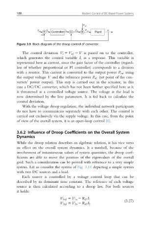
Figure 3.9 Block diagram of the droop control of converter.
The control deviation V e 5 V ref 2 V is passed on to the controller,
which generates the control variable I s as a response. This variable is
represented here as current, since the gain factor of the controller (regard-
less of whether proportional or PI controller) corresponds to a division
with a resistor. This current is converted to the output power P out using
the output voltage V and the reference power P ref (set point of the con-
verters’ power output). This step is carried out in the actuator, in this
case a DC/DC converter, which has not been further specified here as it
is threatened as a controlled voltage source. The voltage at the load is
now determined by the line parameters. It is fed back to calculate the
control deviation.
With the voltage droop regulation, the individual network participants
do not have to communicate separately with each other. The control is
carried out exclusively via the supply voltage. In this case, from the point
of view of the overall system, it is an open-loop control [6].
3.6.2 Influence of Droop Coefficients on the Overall System
Dynamics
While the droop relation describes an algebraic relation, it has vice versa
an effect on the overall system dynamics. It a nutshell, because of the
involvement of instantaneous values of system quantities, the droop coef-
ficients are able to move the position of the eigenvalues of the overall
grid. Such a consideration can be proved with reference to a very simple
system. Let us consider the system of Fig. 3.10 depicting a simple system
with two DC sources and a load.
Each source is controlled by a voltage control loop that can be
described by its dominant time constant. The reference of each voltage
source is then calculated according to a droop law. For both sources
it holds:
V 1ref 5 V 1n 2 R d1 I 1
(3.27)
V 2ref 5 V 2n 2 R d2 I 2