
Page 135 - Modern Control of DC-Based Power Systems
P. 135
Background 99
V
V 0
R 2
R 1
I 2 I 1 I
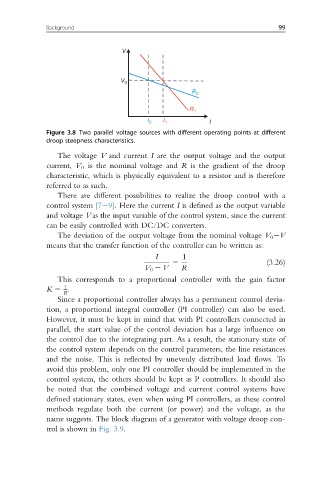
Figure 3.8 Two parallel voltage sources with different operating points at different
droop steepness characteristics.
The voltage V and current I are the output voltage and the output
current, V 0 is the nominal voltage and R is the gradient of the droop
characteristic, which is physically equivalent to a resistor and is therefore
referred to as such.
There are different possibilities to realize the droop control with a
control system [7 9]. Here the current I is defined as the output variable
and voltage V as the input variable of the control system, since the current
can be easily controlled with DC/DC converters.
The deviation of the output voltage from the nominal voltage V 0 V
means that the transfer function of the controller can be written as:
I 1
5 (3.26)
V 0 2 V R
This corresponds to a proportional controller with the gain factor
1
K 5 .
R
Since a proportional controller always has a permanent control devia-
tion, a proportional integral controller (PI controller) can also be used.
However, it must be kept in mind that with PI controllers connected in
parallel, the start value of the control deviation has a large influence on
the control due to the integrating part. As a result, the stationary state of
the control system depends on the control parameters, the line resistances
and the noise. This is reflected by unevenly distributed load flows. To
avoid this problem, only one PI controller should be implemented in the
control system, the others should be kept as P controllers. It should also
be noted that the combined voltage and current control systems have
defined stationary states, even when using PI controllers, as these control
methods regulate both the current (or power) and the voltage, as the
name suggests. The block diagram of a generator with voltage droop con-
trol is shown in Fig. 3.9.