
Page 151 - Modern Control of DC-Based Power Systems
P. 151
Control Approaches for Parallel Source Converter Systems 115
A drawback could be that the centralized model requires a communi-
cation infrastructure that has to be protected against faults as well. That
could be a reason why the LSF controller might not be the best solution
for a real implementation even if its control performance is sufficient.
This is already shown in [3] and [10].
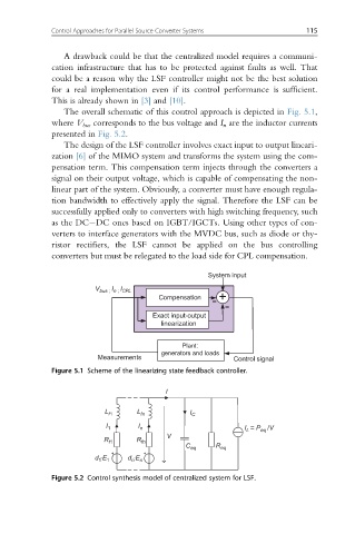
The overall schematic of this control approach is depicted in Fig. 5.1,
where V bus corresponds to the bus voltage and I n are the inductor currents
presented in Fig. 5.2.
The design of the LSF controller involves exact input to output lineari-
zation [6] of the MIMO system and transforms the system using the com-
pensation term. This compensation term injects through the converters a
signal on their output voltage, which is capable of compensating the non-
linear part of the system. Obviously, a converter must have enough regula-
tion bandwidth to effectively apply the signal. Therefore the LSF can be
successfully applied only to converters with high switching frequency, such
as the DC DC ones based on IGBT/IGCTs. Using other types of con-
verters to interface generators with the MVDC bus, such as diode or thy-
ristor rectifiers, the LSF cannot be applied on the bus controlling
converters but must be relegated to the load side for CPL compensation.
System input
V bus ; I n ; I CPL
Compensation +
-
-
Exact input-output
linearization
Plant:
generators and loads
Measurements Control signal
Figure 5.1 Scheme of the linearizing state feedback controller.
I
L f1 L fn I C
I 1 I n I = P eq /V
L
V
R f1 R fn
C eq R eq
d ·E 1 d ·E n
n
1
Figure 5.2 Control synthesis model of centralized system for LSF.