
Page 156 - Modern Control of DC-Based Power Systems
P. 156
120 Modern Control of DC-Based Power Systems
_ V _ V V
C eq L fi P eq
d i 52 2 1 _ V 2 2
S i E i R L C eq C eq v 2 T f C eq T f R L
P eq V 2
_
2 2 2 2ξω 0 V 2 ω VÞ 1 w i
C eq T f V C eq L eq 0
!
C eq L fi 1 1 2
52 2 2 2 ω V
0
S i E i C eq T f R L C eq L eq
!
1 1 P eq P eq
_
1 2 2 2 2ξω 0 V 1 _ V 2 Þ 1 w i (5.32)
R L C eq T f C eq v 2 C eq T f V
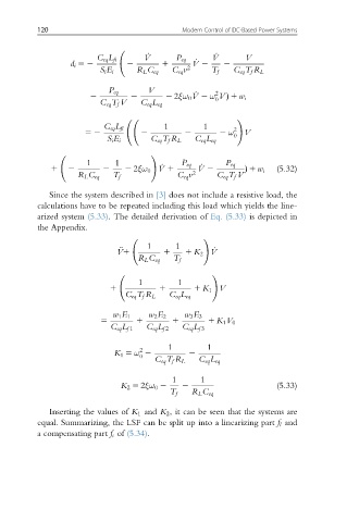
Since the system described in [3] does not include a resistive load, the
calculations have to be repeated including this load which yields the line-
arized system (5.33). The detailed derivation of Eq. (5.33) is depicted in
the Appendix.
!
€
V1 1 1 1 1 K 2 V _
R L C eq T f
!
1 1
1 1 1 K 1 V
C eq T f R L C eq L eq
w 1 E 1 w 2 E 2 w 3 E 3
5 1 1 1 K 1 V 0
C eq L f 1 C eq L f 2 C eq L f 3
1 1
2
K 1 5 ω 2 2
0
C eq T f R L C eq L eq
1 1
K 2 5 2ξω 0 2 2 (5.33)
T f R L C eq
Inserting the values of K 1 and K 2 , it can be seen that the systems are
equal. Summarizing, the LSF can be split up into a linearizing part f l and
a compensating part f c of (5.34).