
Page 157 - Modern Control of DC-Based Power Systems
P. 157
Control Approaches for Parallel Source Converter Systems 121
P eq P eq I CPL I CPL I 2 I R L 2 I CPL
_
f l 52 1 V 52 1
C eq T f V C eq V 2 C eq T f C eq v C eq
(5.34)
_ V 2 I R L 2 I CPL
f c 5 K 1 V 1 K 2 V 5 K 1 V 1 K 2
C eq
With the power sharing factor of 1/3 as three generation side conver-
ters are used.
C eq L fk
(5.35)
F k 5 f l 1 f c Þ
ð
3E k
5.1.3 Simulation Results
5.1.3.1 Cascaded System
A cascaded converter setup has been modeled in Matlab-SIMULINK
with the parameters described in Table 6.1. In the simulation, a step vari-
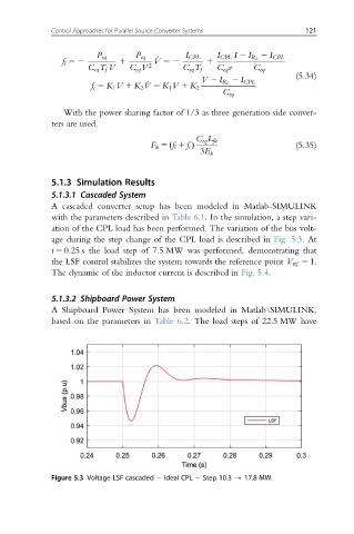
ation of the CPL load has been performed. The variation of the bus volt-
age during the step change of the CPL load is described in Fig. 5.3.At
t 5 0.25 s the load step of 7.5 MW was performed, demonstrating that
the LSF control stabilizes the system towards the reference point V ref 5 1:
The dynamic of the inductor current is described in Fig. 5.4.
5.1.3.2 Shipboard Power System
A Shipboard Power System has been modeled in Matlab\SIMULINK,
based on the parameters in Table 6.2. The load steps of 22.5 MW have
Figure 5.3 Voltage LSF cascaded Ideal CPL Step 10.3 - 17.8 MW.