
Page 195 - Modern Control of DC-Based Power Systems
P. 195
Control Approaches for Parallel Source Converter Systems 159
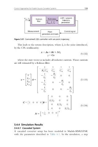
LQR + setpoint
V bus, I Lk Kalman Estimates: trajectory
filter ^ ^ ^
V bus; I L ; I d generation
Measurement Plant: Control signal
generators and loads
Figure 5.31 Centralized LQG controller with set-point trajectory.
This leads to the system description, where I d is the noise introduced,
by the CPL nonlinearity:
_ x 5 Ax 1 Bd 1 NI d
(5.132)
y 5 Cx
where the state vector x includes all inductor currents. Those currents
are still estimated by a Kalman filter.
1 1 1 1
2 3
2
6 R L C eq C eq C eq C eq 7
6 7
2 3 6 1 R f 7
V 6 2 2 0 0 7
6 7
L f L f
6 I L1 7 6 7
x 5 6 7 A 5 6 7 (5.133)
2 0 2 0
I L2
4 5 6 1 R f 7
6 7
I L3 6 L f L f 7
6 7
1
6 7
2 0 0 2
4 R f 5
L f L f
2 3
0 0 0
6 7
E=L f 0
6 0 7
C 5 1 0 0 0 B 5 6 7
0 E=L f
6 7
4 0 5 (5.134)
0 0 E=L f
h 1 i T
N 5 2 C f 0 0 0
5.4.4 Simulation Results
5.4.4.1 Cascaded System
A cascaded converter setup has been modeled in Matlab-SIMULINK
with the parameters described in Table 6.1. In the simulation, a step