
Page 32 - Modern Control of DC-Based Power Systems
P. 32
Introduction xxxi
power converters have to compensate the small-signal negative resistance
behavior of the loads, either through dedicated control algorithms [4,5]
or through forcing disconnection before the MVDC system might oper-
ate out of the stable operative range [6 10].
Nevertheless, the load side stabilizing control approach on ISPSs holds
an unnecessary restriction as it possesses difficulties in standardization and
difficulties in using commercial off-the-shelf converters; hence, every load
converter would have to include a special stabilizing control and would
have to be adapted to the present system before actually inserting a load.
This required adaptation would also be conflicting with the desired
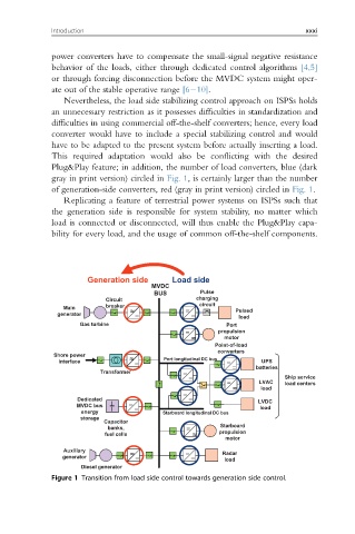
Plug&Play feature; in addition, the number of load converters, blue (dark
gray in print version) circled in Fig. 1, is certainly larger than the number
of generation-side converters, red (gray in print version) circled in Fig. 1.
Replicating a feature of terrestrial power systems on ISPSs such that
the generation side is responsible for system stability, no matter which
load is connected or disconnected, will thus enable the Plug&Play capa-
bility for every load, and the usage of common off-the-shelf components.
Generation side Load side
MVDC
BUS Pulse
Circuit charging
Main breaker _ _ circuit
~ ~ _ _ _ _ Pulsed
generator
load
Gas turbine Port
_ _ propulsion
~ ~ motor
Point-of-load
converters
Shore power
interface ~ ~ _ _ Port longitudinal DC bus _ _ UPS
_ _ batteries
Transformer _ _
_ _ Ship service
_ _
LVAC load centers
~ ~ load
_ _
_ _
Dedicated _ _ LVDC
MVDC bus _ _ load
energy Starboard longitudinal DC bus
storage
Capacitor
banks, _ _ Starboard
fuel cells ~ ~ propulsion
motor
Auxiliary _ _
generator ~ ~ _ _ _ _ Radar
load
Diesel generator
Figure 1 Transition from load side control towards generation side control.