
Page 37 - Modern Control of DC-Based Power Systems
P. 37
2 Modern Control of DC-Based Power Systems
interfaced through a filter circuit consisting of the equivalent series resis-
tor of the inductor r, inductor L and capacitor C with the nonlinear load,
which is represented by a current source with the characteristic P/V, V
denotes the voltage drop over the capacitor.
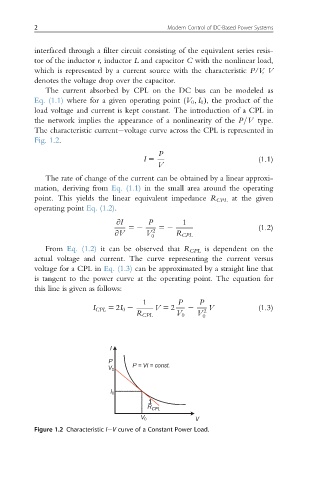
The current absorbed by CPL on the DC bus can be modeled as
Eq. (1.1) where for a given operating point (V 0 ; I 0 Þ, the product of the
load voltage and current is kept constant. The introduction of a CPL in
the network implies the appearance of a nonlinearity of the P=V type.
The characteristic current voltage curve across the CPL is represented in
Fig. 1.2.
P
I 5 (1.1)
V
The rate of change of the current can be obtained by a linear approxi-
mation, deriving from Eq. (1.1) in the small area around the operating
point. This yields the linear equivalent impedance R CPL at the given
operating point Eq. (1.2).
@I P 1
52 52 (1.2)
@V V 2
0 R CPL
From Eq. (1.2) it can be observed that R CPL is dependent on the
actual voltage and current. The curve representing the current versus
voltage for a CPL in Eq. (1.3) can be approximated by a straight line that
is tangent to the power curve at the operating point. The equation for
this line is given as follows:
1 P P
I CPL 5 2I 0 2 V 5 2 2 2 V (1.3)
R CPL V 0 V
0
I
P
P = VI = const.
V 0
I 0
1 ̶
R CPL
V 0 V
Figure 1.2 Characteristic I V curve of a Constant Power Load.